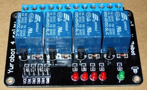
To connect the 4 Relay board to an Arduino is very easy.
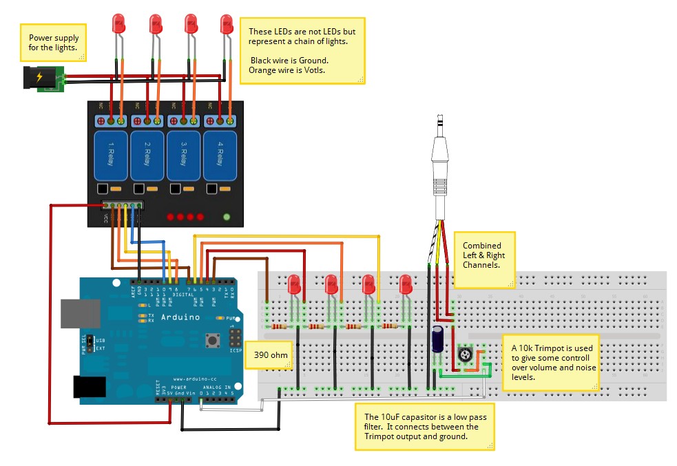
You only need to connect the Arduino +5v to the 4 Relay board VCC pin and an Arduino Ground to the 4 Relay board GND pin.
Then it’s a matter of just connecting some data pins from the Arduino to the 4 Relay board IN pins.
In the example code below I used Arduino pins 7, 8 , 9, 10.
I didn’t use the same digital pins as the LEDs because they are inversed to each other.
The LEDs get power from the Arduino, that means when the digital pin is HIGH (1) it has +5v on the line and the LED lights up.
The relay commands are the opposite to this and the relay is switched with the IN pin is set LOW (0).
The relays default state is to connect COM to NC (normally closed), this is also done by setting the relays IN pin HIGH.
This is a safety feature in-case you Arduino looses power it turns off all the relay switches.
To change the relays state so NO (Normally Open) the pin is set to LOW.
I have some 12v DC lights that I want to activate like LEDs as a VU meter.
To do that I connect the lights power line to the 4 Relay board relay Com connector and
the line to the lights connects to the relays NO connector. The NC connect is left empty.
Example of connecting Lights to the relays.
| Code: Available with purchase |
Other Details:
Specification of 4 Relay board:
Equipped with high-current relay, AC250V 10A ; DC30V 10A
Support 5V voltage
Independent wiring in contact area , safe and reliable
Standard interface that can be expanded in a variety of development boards
Equipped with screw holes for easy installation
Applicable to a variety of platforms including Arduino / AVR / ARM
Size: 7 X 4.9 X1.8 (high) cm
Schematic Diagram:

More information about relays: http://www.kpsec.freeuk.com/components/relay.htm
Tips on working with AC power: … IT IS DANGEROUS !!!...
Only work with AC if you really know what your doing, it can kill.
